Description
This was the final project for EECE2150 Circuits and Signals. In this project, we had to design and make an ECG circuit to measure our own heart rates. We used an AD627 Op Amp and a LT1490 Op Amp that was powered by 1.5 volts for the safety of the user. Once the op-amps were in place to amplify the recorded signal, both a low and high pass filter were built to remove any high frequency noise as well as the DC components of the AD627 respectively. For the high pass, a 6.8µF capacitor, 100kΩ (R) and 200kΩ resistor (Rf) were used. For the low pass, a 2nF capacitor, 400kΩ (R) and 20kΩ (Rs) resistor were used. Once assembled, wires were connected to myself and my heart rate was measured on the oscilloscope. Then an ADC was used to digitally record the signal and further process it on MATLAB. Below are the photos of the schematic and readings. Lab reports for this are avaliable upon request.
Schematics
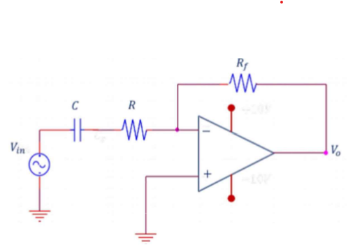
High pass filter schematic
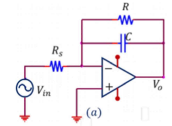
Low pass filter schematic

Path of ECG circuit
Circuit
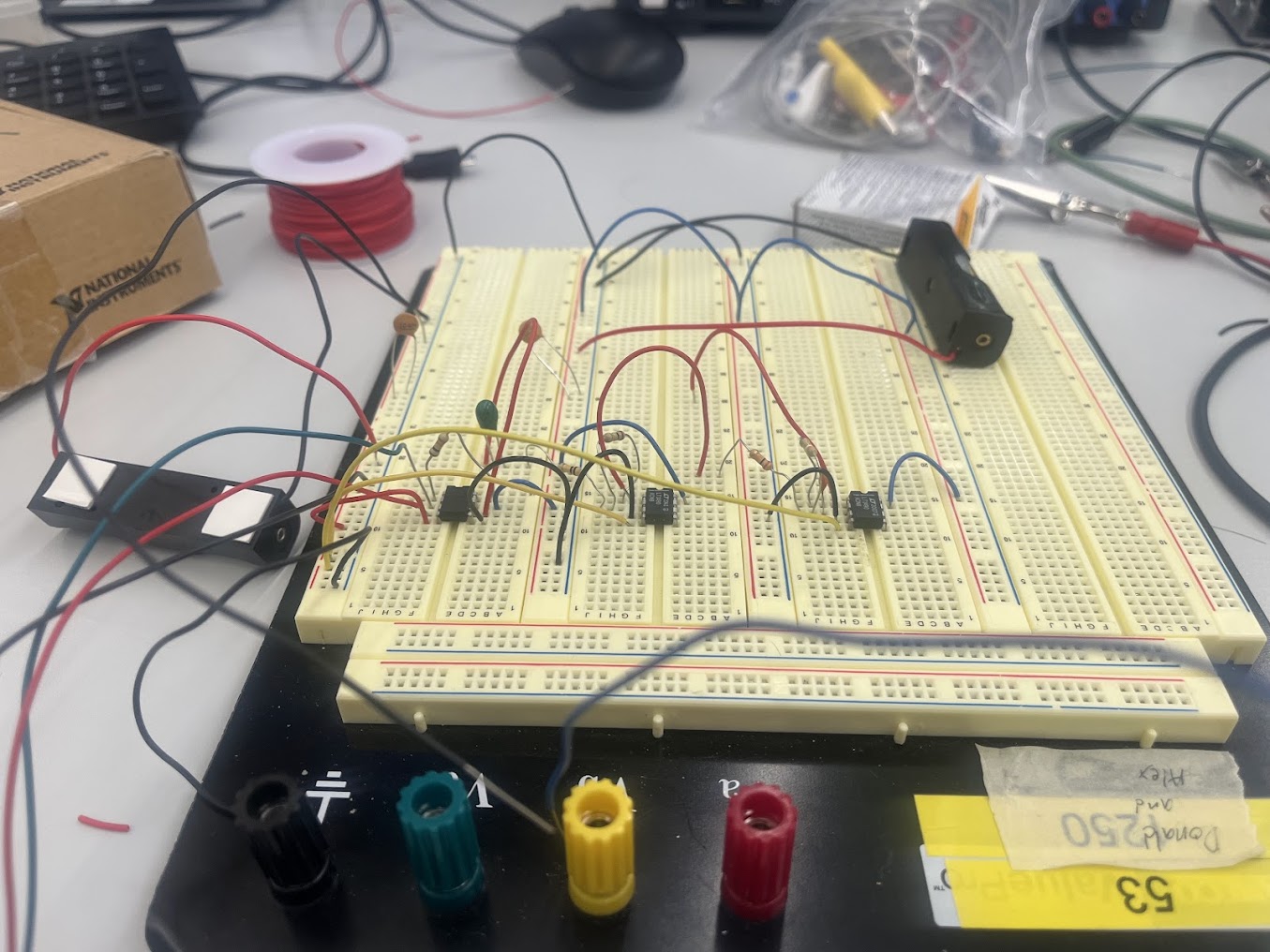
ECG circuit on protoboard
Readings
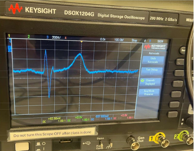
ECG reading on oscilloscope

ECG reading on MATLAB
Next Steps
- Designing a PCB for the circuit